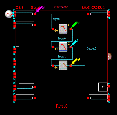
After CAMs have been placed and wired, the circuit visible on the screen can be simulated using AnadigmDesigner®2's built-in simulator.
Figure 1 shows a filter circuit that is ready to be simulated.

Figure 1
To simulate a circuit and view the results, you must create and place at least one signal generator and at least one oscilloscope probe.
You can have up to eight single ended or four differential signal generators per chip. (More if you connect some of them to the disconnected pins of InputCell4 but there would be little reason to do this…)
There is only one oscilloscope and it has 4 probes.
To create a signal generator, use either the simulation menu item "Create Signal Generator," the tool bar icon or by depressing the "G" key, then move the signal generator probe over an input IOcell contact. (Valid connection points will highlight as the signal generator probe is moved close to them)
Click the left mouse button to cause it to connect.
If you try to connect a new signal generator to an invalid location, the signal generator will be deleted. If you try to move an already existing signal generator to an invalid site, the signal generator will snap back to its original location.
Clicking and dragging them using the left mouse button can move signal generators.
Any additional wires connected to the iocell's output terminal will then carry the signal generator's signal to other circuit elements.
Before running the simulation, the user may want to set up simulation options.