All external connections to the DynAMx chips are made via IOCells. IOCells may vary in type. Left double-clicking an IOCell will cause its "Set CAM Parameters " window to be displayed.
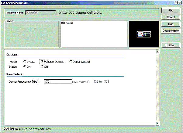
The figure below shows what one of the OTC24000’s output IOCells looks like when its mode has been set to "Voltage Output" and its "Reconstruction Filter" has been turned on.

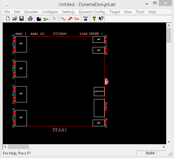
Below is a picture of a "chip". On the left hand side are 4 IOCells, three of them have two inputs and one has 8 inputs for a total of 14 inputs. On the right hand side are output IOCells, each with two outputs. Each IOCell is programmable and is further described in the document available by double-clicking the IOCell icon and selecting "Documentation" from the Dialog Window that appears.

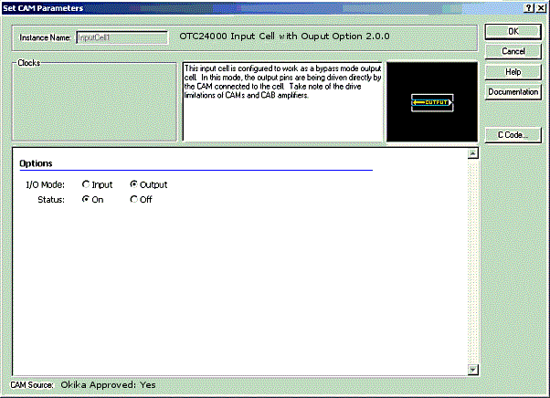
When an IOCell image is double-clicked, a dialog window appears which allows one to set its parameters. The figure below shows the dialog window for the IOCell shown in above.

Note that there is a CAM "Options" field with radio buttons allowing the user to choose the Mode, the output type, and whether reconstruction filtering is to be used. There is also an additional field allowing one to set the corner frequency of the anti-aliasing filter if it is active. Note also that the fields displayed are "dynamic", e.g., choosing "Bypass" for the mode field will cause the "Corner Frequency" field to disappear since "Corner Frequency" is relevant only when the filter is "Active". The "Notes" field is also dynamic and displays relevant information regarding the choices made by the user.
On the right are the standard "OK", "Cancel" and "Help" buttons. "Help" provides help regarding use of the "Set CAM Parameters" dialog window (Figure 3). The "Documentation" button will display help on the CAM itself. The "C Code…" button will display a dialog window offering choices regarding the automatic generation of "C" code that may be used in an application written when the Okika chip is used with a microprocessor of the user’s choice.

On the screen, a reversed Input Cell looks like this:

An Auxiliary IO Cell looks like this:

A RAM Transfer Cell looks like this:

A Digital IO Cell looks like this:

See Also – Differential vs Single-Ended