In AnadigmDesigner®2, the CAMs may contain multiple circuit parameters and architectures that can be selected though CAM configuration. For example, the Bilinear Filter allows the selection of a Low Pass filter, High Pass, All Pass or Pole and Zero filter. The CAM symbol is dynamic. In the example of the Bilinear Filter, the symbol will graphically show which type of filter is selected. Parameters such as gain and corner frequency and the clock frequency used by the CAM can also be modified. The current configuration of a CAM can be viewed by holding the mouse cursor over the CAM symbol. This will trigger a window that will display the current values of all CAM options, parameters and clock settings.
The configuration can be changed in the "Set CAM Parameters" dialog box. This dialog box will appear when a new CAM is selected from a library. It can also be accessed by double-left clicking on the CAM or by right clicking on the CAM and selecting "CAM settings" from the context menu.
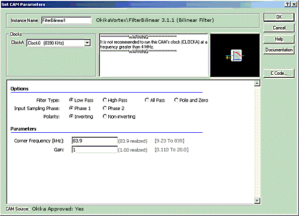
Figure 1: Configuring a CAM
Figure 1 shows the "Set CAM Parameters" dialog box for the example Bilinear Filter. It is configured as a low pass filter with Input Sampling during Phase 2 of the clock. CAM CLOCKA is associated with the chip clock 0, which has a frequency of 8390 kHz. The Corner Frequency is set at a value of 83.9 kHz and the CAM has realized a Corner Frequency of 83.9 kHz. The Gain is set at a value of 1 and the CAM has realized a Gain of 1. These components of the CAM configuration can be changed in this dialog box. Information about the CAM and its options, parameters and clock settings can be accessed by pressing the "Documentation" button. The current configuration will be accepted when the "OK" button is used to close the dialog box, but all changes will be discarded if the "Cancel" button is used instead.
The CAM Options often affect circuit architecture and may affect the chip resources required to implement the CAM. For this reason, if the chip is full of CAMs and additional chip resources are unavailable, certain options may not be available and will therefore be grayed to indicate that they are not selectable. In this case the CAM may provide more information in the "Notes" section of the dialog box.
The CAM Parameters often affect the capacitor values that will be implemented. These parameters have "Limits" on their values. These limits are dynamic and may change based on other parameter values or clock values in the case of clock dependent parameters. Each parameter also has a "Realized" value. This is the value that is actually being implemented by the CAM, based on the current configuration. It should be noted before the "OK" button is pressed that the realized value may differ from the desired value.
A default "Instance Name" will be given to each CAM upon its creation. This name may be changed in the dialog box.
The clock frequency settings are used to associate chip clocks with the clocks required by the CAM. The chip clocks (Clock 0, Clock 1, Clock 2 and Clock 3) are derived from the "Master Clock". These relationships can be set in the "Chip Settings" dialog box. CAMs may require multiple clocks (CLOCKA, CLOCKB, CLOCKC, CLOCKD). The chip clocks can be assigned to CAM clocks with the spinners in the upper left region of the "Set CAM Parameters" dialog box.