IMPORTANT: You should consider setting all settings for each chip before constructing your circuit. Changes to settings will require you to check each marked CAM (Marked with a yellow "?") that has already been placed in that chip (see Configuring CAMs).
Okika Vortex Chips

Clock Settings
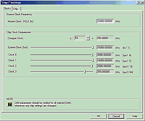
Recall that the Dynamic Analog Matrix is based on switched-capacitor circuits and is therefore a "sampled data system". This means that the Master Clock Frequency sets the sample rate and determines frequency limits for the analog signals being processed by the chip.
You supply the Master Clock Frequency (fc). When you set up the board, you can either use the clock on the chip or an external signal source that you provide.
You should set the Master Clock Frequency in the dialog window above to the frequency of the source in any case. The only effect your setting will have is that AnadigmDesigner®2 software will then be able to properly calculate the realized values that appear in the Set CAM Parameters window associated with each CAM.
The clocks, Chopper, System, Clock 0, Clock 1, Clock 2, and Clock 3 are derived by dividing-down the master clock frequency. Set the chopper value by left mouse-clicking on either the top half or the lower half of the "spinner" button:

Set the values of other clocks by moving the sliders (left-click and drag the slider.)
As shown, the Chopper and System clocks are derived from the Master Clock (fc), while the remaining clocks are derived from the System (fsys) clock.
You can select a particular clock for particular CAMs by using the Set CAM Parameters window associated with that CAM. (see Configuring CAMs).
Whenever you change one or more of the clock frequencies, you should check the parameters of each marked CAM (with a yellow ‘?’) that you have already placed in that chip and readjust those parameters if necessary.
OkikaApex Chips

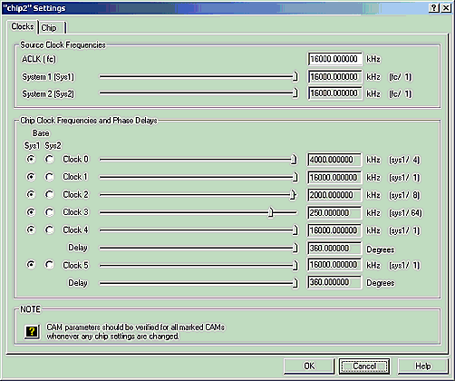
ACLK is the master clock for the chip. Its frequency is fc.
System 1 clock is derived from fc and can be scaled down. It is used as a base for other clocks.
System 2 clock is derived from fc and can be scaled down. It is used as a base for other clocks.
Clock 0 through Clock 4 can be based either off of Sys1 or Sys2. Their frequencies may be further divided down to lower frequencies.
Clock 4 and Clock5 are similar to Clocks 0 through 4. In addition, a phase delay can be specified for clocks 4 and 5. Phase delay will need to be set for certain CAMs. Phase delay settings will be described in the CAM documentation for those CAMs which make use of Phase delay. Note: The phase delay in clock periods is clock divider * (delay in degrees/360.0). The clock divider is the divider being displayed for whichever system clock (sys1 or sys2) is being used.
You can select a particular clock for a particular CAM by using the Set CAM Parameters window associated with that CAM. (See Configuring CAMs).
Whenever you change one or more of the clock frequencies, you should check the parameters of each CAM that is marked with a yellow ‘?’ and readjust those parameters if necessary.