User Interface
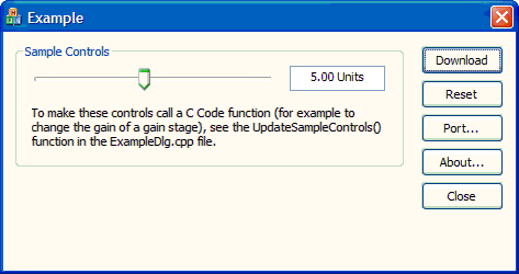
The Visual C++ Prototyping tool generates a fully functional user interface that is ready for immediate use. The interface has buttons to download the configuration to development board, setup port communications, and reset the chips on the development board. If your circuit schematic has multiple chips with the same device ID, for the purpose of switching between multiple states within a single device, the tool will also generate buttons for switching between those states. Sample slider\edit controls are also provided as an example of how sliders can be used to control dynamic C Code functionality.

Description of button controls
·The download button action will depend upon the configuration of the hardware:
oSingle Chip Design
For a single chip design, or a single chip design with multiple states, the OnDownload() function contains a single line of code:
m_chipName.ExecutePrimaryConfig();
This function sends the primary configuration data for chipName to the development board using the already open communications port. Port communications are discussed below in Port Communications.
oSingle Chip Design with States
For schematics that use multiple chips to represent different states of a single device, the tool generates an additional button for each chip. These buttons are automatically set to call ProjectNameDlg::OnStateNumber() functions, and are named based on the chips in the schematic.
These state buttons can be pressed after the Download button, and use C Code dynamic reconfiguration to change the device to a different state without having to reset it and do another primary configuration.
oMultiple Chip Design
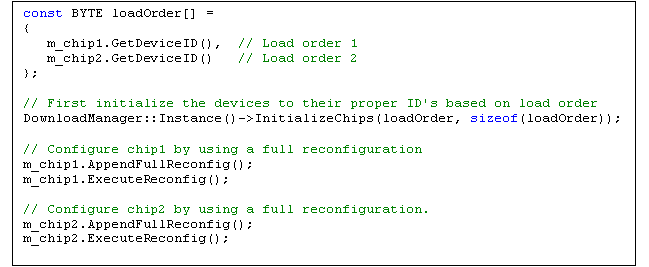
For a multiple chip design the code first uses the InitializeChips function of the DownloadManager class to initialize all devices on the development board with the proper device IDs in the load order specified in AnadigmDesigner®2.
For each chip in the design it then calls the following two functions:
m_chipName.AppendFullReconfig();
m_chipName.ExecuteReconfig();
This adds the entire configuration data required to program the device to the reconfiguration buffer, and then immediately executes the reconfiguration. A primary configuration is not performed since all device IDs were setup in the call to the InitializeChips function.
The InitializeChips function and the ExecuteReconfig() function both require an open communications port. Port communications are below in Port Communications.
·The "Reset" button causes a RESET command to be sent to the Okika Development Board via whichever Serial or Parallel port was selected by use of the "Port…" button.
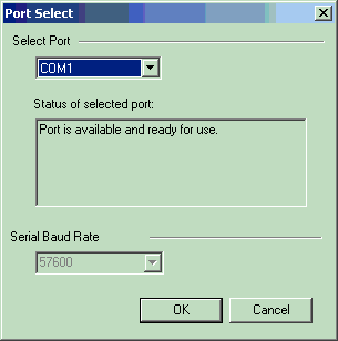
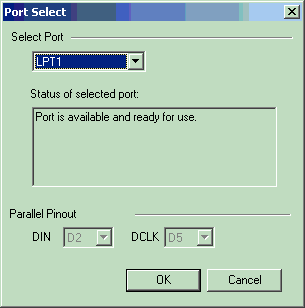
·The "Port…" button brings up a "Port Selection" dialog window that allows you to select the port you wish to use. You can use either a serial or a parallel port. You would of course need to have the appropriate cable available. Note that the advantage of the parallel port is its speed. Dynamic control of C Code functions over the serial port will not provide results as "smooth" as the results obtainable through use of the parallel port.

Serial port COM1 selected.

Parallel Port LPT1 selected. Note that the parallel port pins D2 and D5 carry the information that the Okika Development Board will be using. These pins will be "bit-banged" by code that is in the PortIO subsystem that is part of the generated Osc example project.
·The About button brings up a standard "About box" which is used to display information about your application. It can be modified through the Resource View IDD_ABOUTBOX dialog resource within Microsoft Visual C++.
·The "Close" button closes the application.
Description of Sample Controls
·Usage
To make the sample controls call one of the generated C Code functions takes only a few lines of code. The first step is to setup the initial value and the desired range of values for the slider. This is done in the ProjectNameDlg::OnInitDialog() function with the following lines of code:
m_sampleMin = 2.0;
m_sampleMax = 8.5;
m_sampleValue = 5.0;
Next, you call the desired C Code functions in the ProjectNameDlg::UpdateSampleControls() function using the value of m_sampleValue For example:
m_chip1.GainHalf1.setGain(m_sampleValue);
m_chip1.ExecuteReconfig();
·Details
A sample slider control and edit box are generated to provide example code on their use. The example code demonstrates linking the value of the slider and edit control, constraining the input values to a given range, and formatting the edit box with a value and its units.
The slider and edit controls are found as private member variables of the ProjectNameDlg class:
CEdit m_sampleEdit;
CSliderCtrl m_sampleSlider;
These member variables are linked to the slider and edit box on the user interface by the following lines of code found in the ProjectNameDlg::DoDataExchange(CDataExchange* pDX) function:
DDX_Control(pDX, IDC_SAMPLE_SLIDER, m_sampleSlider);
DDX_Control(pDX, IDC_SAMPLE_EDIT, m_sampleEdit);
This makes it possible to directly query and manipulate the slider and edit box using the m_sampleEdit and m_sampleSlider member variables.
The ProjectNameDlg::OnHScroll(UINT nSBCode, UINT nPos, CScrollBar* pScrollBar) function is the MFC function that is called when a slider is adjusted by the user. To tell MFC to call this function for us, the ON_WM_HSCROLL() macro is inserted into the dialog’s message map between the BEGIN_MESSAGE_MAP(ProjectNameDlg, CDialog) and END_MESSAGE_MAP() lines. This function is called when any horizontal slider is adjusted, so it is necessary to determine which slider is actually changing.
Two methods are used to detect when a new value is entered into the edit box. The first checks for a changed value when the edit box loses focus. This is done by adding ON_EN_KILLFOCUS(IDC_SAMPLE_EDIT, OnSampleEditChanged) to the dialog’s message map and adding the ProjectNameDlg::OnSampleEditChanged() function. The second method checks for the user pressing the Enter key when the focus is on the edit box. This is done in an override of the MFC CDialog virtual PreTranslateMessage(MSG* pMsg) function.
Each of these functions eventually calls the ProjectNameDlg::UpdateSampleControls() function, which handles updating the position of the scrollbar, updating the text of the edit box, and updating the value of m_sampleValue. Any code you add that uses m_sampleValue to control C Code should be inserted at the end of the UpdateSampleControls() function.
Port Communications
All of the necessary code required to communicate with the development board via the serial or parallel port is generated by the tool. This code can be found in the PortIO project. The main C++ class to instantiate and use for port communications is the Port class. The Port class contains various methods for opening and closing the port, sending configuration data to the board, and reading back board settings. The class also contains methods for getting and setting specific port settings (such as baud rate or port name), as well as methods for saving and restoring the port settings from a registry key.
An instance of the Port class is created for you as a private member variable of the DownloadManager class, so it is not necessary to use the Port class directly.
The DownloadManager class has the following functions for using the port:

Calls to the LoadPortSettings and SavePortSettings functions are generated by the tool, so it is not necessary for you to add code to save and restore the port settings across runs of your application. (These calls can be found in the ProjectName.cpp file).
The functions of the DownloadManager class can be called from the ProjectNameDlg.cpp file (or any other .cpp file that contains #include "DownloadManager.h" at the top). The DownloadManager class is not meant to be created directly, but rather you use a single global instance of the class that is created for you. This is done by using the Instance() method of the DownloadManager class:
DownloadManager::Instance()->OpenPort();
DownloadManager::Instance()->ShowPortDlg();
C Code Wrappers
The C Code generated by AnadigmDesigner®2 is found in the CCode project. In addition to the C Code, the tool also generated C++ class wrappers for each reconfigurable CAM and chip, as well as the DownloadManager class which is responsible for using the Port class to communicate with the development board.
CAMs
A C++ class is generated for each reconfigurable CAM in the AnadigmDesigner®2 schematic. The names of the generated classes are in the form chipName_camName. Each CAM class contains functions that wrap the underlying C Code functions that are available for controlling the CAM.
Calling the functions of the CAM wrapper classes does not immediately download the reconfiguration data to the board. This enables multiple C Code functions to be called and their cumulative results downloaded at some later time. To download all pending C Code changes, the ExecuteReconfig() function of the generated chip should be called.
Chips
A C++ class is generated for each chip that contains reconfigurable CAMs on the AnadigmDesigner®2 schematic. The names of the generated class are based directly on the name of the chip they represent.
·Common Functions
Every chip class shares the following common functions:
·an_Byte GetDeviceID()
Returns the device ID of the chip.
·void ExecutePrimaryConfig()
Resets all devices on the development board and downloads the primary configuration data for the chip. Since this method resets all devices on the board, it should not be used to configure chips on a multiple device board. Instead, use the InitializeChips function of the DownloadManager class, as described below in the DownloadManager Class.
·void ExecuteReconfig()
Downloads any pending reconfiguration data for the chip and immediately clears the reconfiguration data buffer. If there is no data in the reconfiguration data buffer this function does nothing.
·void ExecuteReset()
Resets the device that has been initialized with the device ID of this chip. To reset chips on a multiple device board, it is preferable to call the ResetChips function of the DownloadManager class.
·void AppendFullReconfig()
Appends all of the data required fully program the chip to the reconfiguration buffer. This allows the chip to be reset to its default state without actually having to reset the device and send a primary configuration. This method should be used in combination with the InitializeChips function of the DownloadManager class to configure a multiple device board.
This method does not immediately download the configuration to the board. This enables further C Code functions for CAMs in the chip to be called and their cumulative results downloaded at some later time.
·CAM Member Variables
For convenience, each chip wrapper class contains an instance of a CAM class wrapper for each if its reconfigurable CAMs. For instance, if chip1 contained two CAMs named GainLeft and GainRight, the following code would be found in the chip1 class in the chip1.h header file:

You should never need to directly create an instance of a CAM wrapper class. Instead, you should use the instance of the CAM wrapper class that is declared in the chip class.
An instance of each chip wrapper class is automatically declared as a member variable of the ProjectNameDlg class as m_chipName. This allows you to immediately begin calling C Code functions for any reconfigurable chip or CAM from within ProjectNameDlg. For example, a function ChangeGain could be added to the class, and the code could look like this:

The DownloadManager Class
The DownloadManager class is the gatekeeper of port communications. All calls to download data to the development board eventually go through the DownloadManager.
The DownloadManager is a single-instance class, meaning you cannot directly create a new instance of a DownloadManager. Instead, you must use the static Instance() method of the class to access the single existing instance of the class. For instance, the ResetChips() function would be called like this:
DownloadManager::Instance()->ResetChips();
Before calling any of the chip Execute*() functions that download data, a port must first be opened with the DownloadManager. Call the ShowPortDlg() function to open a window that allows the user to select a port. The Port… button on the user interface is already hooked up to call this function. To save and restore the user’s port selection between runs of the application use the LoadPortSettings and SavePortSettings functions, which take a CString parameter that indicates the registry key from which to save and load the settings. The CString should be in the form "CompanyName\\ApplicationName". Calls to the LoadPortSettings and SavePortSettings functions are generated by the tool, so it is not necessary for you to add this code.
The DownloadBits function is used by all the chip Execute*() functions to download data to the board. This function simply takes an array of BYTEs and sends them to the open port.
The ResetChips function is used to reset all chips on a multi-chip board. If your board has only a single chip, the ExecuteReset() function of the chip class could be used instead.
The InitializeChips function is used to initialize all chips on a multi-chip board with the proper device IDs in the correct load order. The function takes as a parameter an array of device IDs that should be ordered from lowest to highest load order. This function does not download any configuration data, but rather just does a blank primary configuration on each chip for the purpose of setting up the device IDs. After this function is called, each chip can be configured by doing a full reconfiguration (not a primary configuration). For example:
