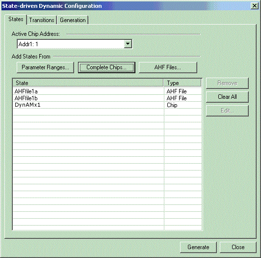
This window is used to manage the circuits and groups that will be used with State-driven Dynamic Configuration.

States Tab
The States Tab provides control over which chip’s contents and which AHF files are available for creating various states. It also allows additional states to be generated for any or all parameters of CAMs that are present within the listed circuits.
Active Chip Address
The "active chip" is the chip on the screen that is outlined in red. You click on empty space within a chip to make it "active". This is not, however what is meant in the state-driven dynamic configuration subsystem. In the state-driven dynamic configuration subsystem the "active chip" is simply the chip on the screen that is to be the current focus of attention for state-driven dynamic configuration operations.
A chip’s chip address shows up as "Addr1" at the top left corner of an DynAMx chip on the screen.
The chip address, Addr1, is used as a chip select so that updates can be sent to a particular chip.
In an embedded system with multiple DynAMx chips, the chip address is used to direct the proper updates to the proper chip.
It is important that any generated AHF files that will be used for state-driven dynamic configuration purposes be generated using the chip address of the appropriate chip on the target board, i.e., the addresses must match so that the configuration data will go to the correct chip.
The active chip on the screen during state-driven dynamic configuration setup must also have a matching Addr1 field.
In the example above, the chip address is 1.
Add States From…
Circuit states can come either from chips on the screen or from AHF files that have been saved.
Complete Chips…
Clicking on this button will bring up a chip selection window.
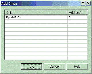
This will display a list of chips whose address (Addr1) field matches the "Active Chip Address" in the main window. In this case the address is 1 so the listing shows DynAMx1 whose chip address also happens to be 1.
AHF Files…
AHF files must contain the proper chip address (Addr1) and they must match the chip type of the target chip, i.e., OTC24000 configuration data cannot be loaded into an OTC24000 chip.
AHF files typically are saved ahead of time. A simple example would be to save several AHF files each of which contains a different setting for a gain parameter. Each AHF file would represent one "state" of the circuit. More complex examples might involve saving circuit states where the circuit topology actually changes, i.e., different CAMs with different wires and different parameters.
Parameter Ranges…
It is now possible to create states where parameters are stepped through a series of values. For example if you wanted to create 5 states where the gain of some CAM is set to 1, 2, 3, 4, and 5, you could change the gain parameter and save an AHF file for each of the 5 gain values. Or you could use the "Parameter Ranges" function to automatically build the 5 states.
Clicking on "Parameter Ranges…" in the "State-Driven Dynamic Configuration" window shown above will result in the following window whose content is dependent upon the CAMs that were created in DynAMx1:
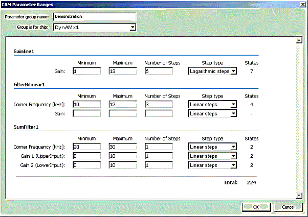
We see in the above that three CAMs exist within DynAMx1.
We must enter a "Parameter Group Name". It can be any alphanumeric name desired.
We see from the above that three CAMs exist within DynAMx1. There is a GainInv stage, a FilterBilinear stage, and a SumFilter stage.
Each of the CAMs has a set of parameters. The FilterBilinear CAM has Corner Frequency and Gain parameters.
By typing in a minimum number, a maximum number, and a number of steps, we set can the system up so that it will generate a set of states for all of the parameter steps.
For example, if we work with the GainInv1 stage, and enter 1, 13, and 6, then the system will be set up to generate 7 states. The states will have gains of 1, 2, 4, 6, 8, 10, and 12.
There is also an option to space the steps logarithmically.
The number of states for each CAM is shown and the grand total for all states of all CAMs that have been stepped is also shown. Note that the above example defines 17 states. The "Total:" field shows how many overall states would be generated. It is 7 * 4 * 2 * 2 * 2 = 224.
Transitions Tab
The "Transitions" tab lets you choose which state transitions to include in your generated C code. You can either choose ALL transitions:
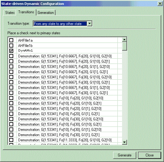
All transitions
Or you can choose selected transitions:
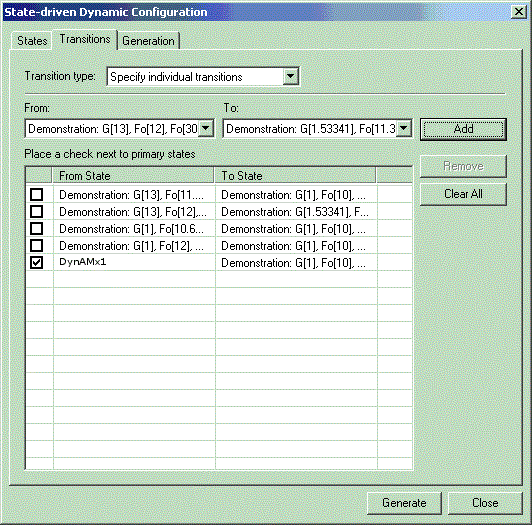
Selected transitions
Transitions can be added by selecting "From" and "To" states and then clicking "Add".
Generation Tab
The Generation Tab allows the configuration data parameters to be set. It is possible to generate C code, C-formatted text files or AHF files. For the latter two options, it is possible to generate one file containing all of the transition data or to generate multiple files each of which contains data for one transition.
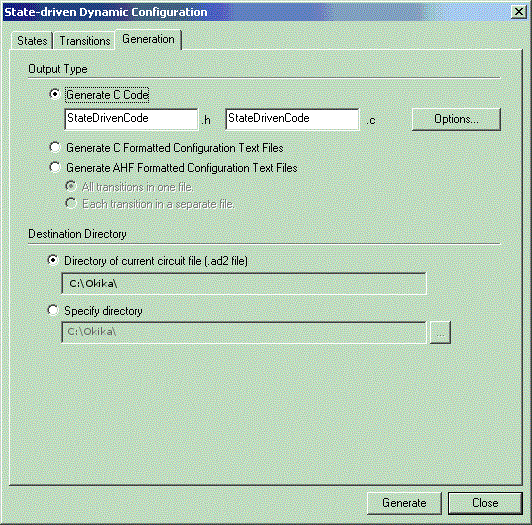
This also allows choice of the directory wherein the generated files will be placed.
There are also C code generation options that allow more control over the names used in the generated C code.
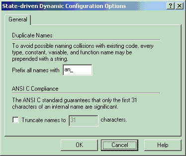
Generated C Code
When "Generate" is selected, the chosen output (AHF files or C Code) will be created in the directory that was chosen as the destination directory.
If C code is being generated, two files will result, a C file and its accompanying H file.
The .c file contains two main areas, a configuration data area and a "Functions" area. There are two functions, one to retrieve configuration bytes for a primary configuration stream and the other to retrieve configuration bytes for a transition.
The header file (.h file) contains a mapping of each transition to an integer. The functions in the .c file can be used to retrieve configuration bytes for any one of the listed transitions in the .h file.
Configuration data is labeled using the CAM parameter names and the parameter values specified for a particular transition, e.g.,
an_Demonstration_G153341_Fo113333_Fo30_G11_G21_Data.
In an embedded system, the retrieval functions would be used to get the appropriate configuration data for a particular circuit state and then would be transmitted to the FPPA chip by whatever means is available within the embedded system.
See API Functions