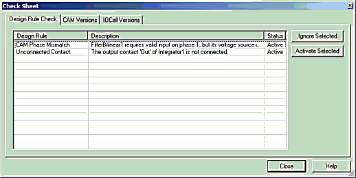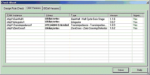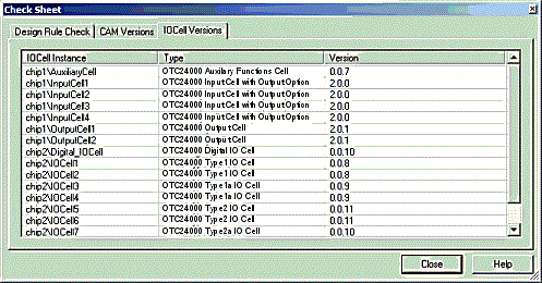
The check sheet command runs a design rule check, a CAM version check, and an IOCell version check for the current circuit. The design rule check checks the current circuit for circuit design issues. The version check compares the versions of CAMs and IOCells used in the circuit with the versions of their counterparts in the current AnadigmDesigner®2 libraries.
Design Rule Checks
Overview
DynAMxis a powerful tool that offers correct-by-construction design and ease of use. The software will generate a circuit exactly as it is designed on the DynAMx design surface. However, it is possible that a circuit, though realizable in silicon, violates certain design principles known to cause unexpected or unintended results. AnadigmDesigner®2 monitors the circuit and continuously checks for known circuit design issues. Each issue that the software finds will be indicated with a visual cue on the AnadigmDesigner®2 design surface, and listed in detail on the Design Rule Check tab of the Check Sheet.
Design Rule Check Sheet

Ignoring Rules
There are cases where DynAMxmay indicate a design rule violation for something that was done intentionally. When this occurs it may be desirable to hide the visual cue that is displayed on the DynAMx design surface. To do this, select the issue in the Check Sheet and click the Ignore Selected button.
Note: This ignores only the selected instance of a design rule, and not the design rule in general.
Design Rules
CAM to CAM Phase Mismatch
This issue occurs when an input contact requires valid input on a phase in which the source contact does not have valid output.
DynAMx will display a dashed wire between the offending contacts.

CAM to CAM Sample Clock Path Mismatch
This issue occurs when the sample clock frequency of an input contact differs from the sample clock frequency of its source contact.
DynAMx will display a dashed wire between the offending contacts.

CAM Parameters Invalid Due to Change in Power Settings
The parameters of some CAMs are dependent on the power settings of the chip. If the power settings of the chip are changed, it is necessary to check each power dependent CAM to ensure its parameter values are valid.
DynAMxwill display a ‘?’ next to each affected CAM.

CAM Parameters Invalid Due to Change in Clock Frequency
The parameters of some CAMs are dependent on the CAM’s sample clock frequency. If the clock frequencies of the chip are changed, thereby changing the sample clock frequency of CAMs, it is necessary to check each frequency-dependent CAM to ensure its parameter values are valid.
DynAMxwill display a ‘?’ next to each affected CAM.

Chip Sample Clock Frequency out of Recommended Range
This issue occurs if the frequency of a chip clock falls outside of the recommended sample clock frequency range of the chip.
DynAMx will display a ‘?’ next to the name of the chip.

Chip Chopper Clock Frequency out of Recommended Range
This issue occurs if the frequency of a chip’s chopper clock falls outside of the recommended chopper clock frequency range of the chip.
DynAMx will display a ‘?’ next to the name of the chip.

Chip has an Unsafe Device ID
Chip Address1 values of 255 and 213 should not be used. (255 will cause all chips in a multi-chip circuit to respond. 213 is equivalent to a "sync" byte and may cause a download problem.)
DynAMx will display a ‘?’ above the offending Chip Address1 value.

Unconnected Contact
DynAMx displays all unconnected contacts as red circles with yellow outlines. Connected contacts are displayed as red squares with no outline.
Note: This design rule does not apply to IOCells.

CAM Versions
The second tab, CAM Versions, lists all CAMs that are in the current circuit:

·CAM Instance – The fully qualified name of the CAM (chip name / cam name)
·Library – The library from which this CAM was originally loaded
·Type – The type of CAM
·Version – The version of the CAM that is in the circuit. If a different version is available in the library, it will be listed in parenthesis.
·Approved - CAMs that are Okika Approved CAMs will display a green "Yes", while those that are not approved will display a red "No".
IOCell Versions
The third tab, IOCell Versions, is similar to the CAM Versions tab but give the status of the IOCells within each chip.

·IOCell Instance – The fully qualified name of the IOCell (chip name / IOCell name)
·Type – The type of IOCell
·Version – The version of the IOCell that is in the circuit. If a different version is available in the library, it will be listed in parenthesis.